Tuesday, March 29, 2011

Make an Infrared Remote Control for PC

A friend of mine came yesterday to me asking if I can do something for him to control WinAmp via a Remote Control. After some searching I found a very simple to build IR receiver using the serial port on LIRC official page so I started to gather the components from our local electronics shop. It costed me around 1.5$ so it was also cheap enough :D .
The schematic is


and the components are as follows :
  • IC1 = 78L05, 5V regulator
  • IC2 = TSOP1738 , IR receiver
  • D1 = 1N4148
  • C1 = 4.7uF
  • R1 = 4.7K
  • one male or female (depends on your configuration/cables) serial (DB9,RS232) connector

I choosed to put all components on air and in the serial connector’s box (photos below).
The pinouts of the 9-pins connector are :

  • 1 = DCD (Carrier Detect)
  • 2 = RXD (Receive Data)
  • 3 = TXD (Transmit Data)
  • 4 = DTR (Data Terminal Ready)
  • 5 = GND (Ground)
  • 6 = DSR (Data Set Ready)
  • 7 = RTS (Request To Send)
  • 8 = CTS (Clear To Send)
  • 9 = RI (Ring Indicator)
TSOP1738 pinouts

IM000144.JPG
the starting materials

IM000148.JPG
during construction

IM000158.JPG
inside the box

IM000159.JPG
the final product

IM000387.JPG
the remote controls I use
For the software part you can use :

(Edited) As a remote control you can use almost all universal remote controls (you must know its working code for the TSOP1738, for the one from the attached picture the code is 081) and most of the domestic (videorecorder, tv …) remote controls. To see if one is working open WinLirc, press Reconfigure and then Raw Codes. If when you press a button on your remote control you see lots of numbers there then it means it is working.

(Edited) To add a status LED to your receiver, just make the schematic below (I tested it last week and it went ok). The disadvantage of this is that you’ll need a battery so it can run ok.

http://stuff.nekhbet.ro/wp-content/uploads/2007/11/diy_in_receiver_status_led6.gif

Just click the image to see it larger

Hand made GPS receiver


I had bought MStar GPS module for UAV Board. But the datasheet is not very clear for this one. So I have made a test board for test it.

DIY RF Receiver


If you're a hobbyist or just have a fondness for radio, you can make your own RF receiver. Radio frequency receivers have numerous uses, but they often act to pick up local radio stations. You can buy an RF receiver, but that's not nearly as fun as making one yourself. That way, every time a signal comes through, you'll have validation for a job well done.


Instructions

    • 1

      Cut two sets of holes near the top side of your stiff plastic bottle with the nail about a half an inch apart. Parallel to the holes, punch two sets of holes near the bottom of the stiff bottle.

    • 2

      Push one end of the magnet wire through the holes near the top side. Pull through about eight inches of wire. Wrap the long end of the wire down the body of the stiff bottle. Make sure each wrap of the wire comes in contact with the last full wrap. As you wrap the wire, loop every fifth wrap around the pencil. These wire loops will be referred to as wire taps. Wrap this pattern until you get to the bottom of the bottle. Push the end of the wire though the holes at near the bottom side of the stiff bottle.

    • 3

      Strip the vinyl coating from the ends of the wire wrap at the top and bottom of the bottle with your wire cutters. Take care not to cut the wire. Carefully remove the vinyl coating from the wire taps. Take care in not removing too much, as you don't want to remove coating from the wire areas wrapped around the bottle.

    • 4

      Solder one end of the Germanium diode to the end of the wire at the bottom of the bottle.

    • 5

      Snip off the end of the cord to your corded phone handset. Strip off the protective covering to reveal the interior wiring. Find the transmitting yellow and blue wires. Solder the blue one to the free end of the Germanium diode. Solder the yellow wire to the free end of the magnet wire at the top of the bottle.

    • 6

      Clip and attach one end of the alligator jumper to a bare spot on the magnet wire you soldered the yellow wire. Clip and attach the other end of the alligator jumper to a piece of metal that's firm into the ground. This could be something like a pipe.

    • 7

      Clip and attach one end of the other alligator clip to the end of the insulated wire. Attach the insulated wire to a high spot like your roof or a tree branch. This will act as your antenna. Clip and attach the other end of the alligator jumper to one of the wire taps. Use the wire taps to adjust the station your RF receiver will pick up.


Monday, June 28, 2010

Stereo FM receiver using TA7640 and TA7343

use a car's FM Tuner RF Frond End ICs as IF and IC TA7640 TA7343 as Stereo Encoder, results were very memuasakan resultant highly stereo sound separation of L and R sounds so obvious when 100% of its components come from the junk.

PCB

End Results

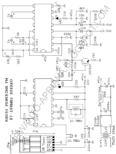
Stereo FM receiver using LA1260 and LA3361

FM receiver circuit redesign is the result of the Kit-Kit oft-sold in the market with IC LA1260 and LA3361 datasheets, so I think it produces better stereo sound ...

THIS is the circuit ...

After everything is assembled to PCB


Blue Tooth GPS Receiver - Turn Your PDA Into A GPS

Bluetooth is a new wireless technology to hit the market. This allows users to connect mobile phones, PDAs, laptops and all the various gadgets with one another to transfer data without cables boring and annoying. The time required to transfer files is the same as that required for the same email. Now it's only logical that runs in a Bluetooth GPS receiver will be created.


Now the GPS bluetooth receiver just changes your PDA into the GPS receiver itself. PDAs So now you can tell exactly where you are on earth. The main advantage in buying a bluetooth gps receiver is that it eliminates the need to buy a gps device itself. Bluetooth GPS receiver allows users to download a specific location on the map or instructions directly to the PDA. Previously involved with cable technology, now do not need cable.


It definitely helps to have a PDA compatible Bluetooth GPS receiver. If your PDA is not compatible, then the adapter can be purchased and inserted into your PDA or flash drive to any other suitable slots for the adapter. Now you may be thinking that downloading all of this data will not need to slow down and obstruct the PDA, but all the information that you download like a map and check point can only be loaded into the memory stick which in turn can be inserted into a memory expansion slot on your PDA. This leaves you free compact flash slot for connecting other devices.


Life is definitely easier when you also gps your PDA. Just place your Bluetooth GPS receiver while driving toward the heavens open and easy to find points of interest along your route whether it is restaurants, cinemas, hotels, hospitals and anything else that might want to know the way to or from. PDAs will be converted to display and easy to read that give you easy to read and understand the directions from your location to the destination you want. All of this without annoying cables into the crease!


With all these electronic gadgets to make life easier in the vicinity and created more and more everyday is a Bluetooth GPS receiver to make things easier on or off the road without your having to buy an extra gadget at all!

Experiment: A Simple Receiver - Radio Receiver AM


Today we will discuss how to create a Receiver / AM radio receiver is simple. Actually this is a tool that I made during the period of the Final Project and Practical Introduction to Telecommunications Systems chance drawings can be obtained with a complete picture of the Sci-Toys.com.

What ingredients in making this AM Receiver / Receiver Radio this AM?
1. Sturdy plastic bottle. Smoking's size ... but yesterday I was using for the project bottle apple juice remaining Sunfresh which has a diameter of approximately 7.5 cm. My advice try to be bigger than that caught more variable frequency.
2. A roll of coated copper wire with email. If the same confused way what the seller told . Why use a coated cable email? Simple, so that no short loops. When asked how the diameter of the diameter of the cord simply use I've tested that is 0.8 mm. Oh yea i thing, in Indonesia are usually old email will be golden yellow in color, so do not be confused to find the green wire as shown.
3. A germanium diode types. 1N34A type that is recommended , my advice is still do not see you can try to type 1N60A Same function, I have tried and can function properly.
4. A high impedance speakers. In this project we use the existing speakers in the telephone receiver, if you do not want to sacrifice your phone, just buy speakers that membranes of translucent colored plastic instead of ordinary speaker2 membranes from the barrier of black paper inside Impedance 8 Ohm only.
5. Some cable attached alligator claws. We use this much because we want to project this time free solder soldering.
6. Antenna. We can use anything for a long iron main antenna or cable can be used as a bare antenna . But I recommend using External TV antenna.

Part1. AM receiver coil (Receiver)

Make your bottle looks like the picture below


As many as two holes respectively on the bottom and the bottle, do not worry too good because it is only used as a place to tie the cable loops that had you bought.


Enter our coil cord and remove the bit length of the hole that only approximately 15 cm, if it is still rather loose one more repeat loop until cord loops can not move anymore. (Actually this is not too important, just make such a way that does not move when windings are made later.)


Now take a part of a long coil and wrap the body of the bottle. Every five loops make a small loop, so you can easily tuck it inside pencil's coil. repeat until touching the bottom of the bottle.


Have looked like in the picture? if so, do not forget to tie the end of the 2 nd winding hole below the bottle so that no loose loops ... then cut the cable at the end of the nd of equal length with wires protruding on the upper side of the bottle that is about 15 cm.


If you already Peel email attached at both ends of the cable that was 15 cm and a small loop on the loop that we created earlier, so that the original copper cable in sight.

Prepare also your telephone receiver, cut the cord and find the red and white cables.


Part 2. AM receiver circuit (Receiver)


Do not Confused to see the image above! diodes that wrap your purchases in a 15 cm coil wire at the bottom of the bottle with a black head of diode negative toward the speaker (white cables on the speakers). Connect the cable is also above 15 cm of positive bottles with Speaker (Red cable) and cable capitkan an alligator claw (claw Green in picture) at this nexus and capitkan the claws of one another on the same cable to the Grounding vera good (or Body Land you own).

Do not forget to mencapitkan a crocodile Fruit cable again to one loop in the coil (yellow claws), and capitkan other end to TV Antenna.

Part 3. Testing

If all components are connected correctly, then when it is connected to the antenna and the Grounding which can be good we should be able to hear the radio broadcast.

Try to replace loop with loop tercapitkan beside it, then we ought to be able to hear radio broadcasts from a different frequency.