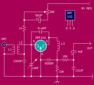
 The circuit is very simple, but necessary experience in assembling the recipient this. This circuit can receive the frequencies from 140 to 150 MHz covering the frequency of 2 meters.There is a super-regenerative detector that can set this to be very sensitive receiver. This receiver can receive the transmission signal from a transmitter that is 10th mile, with only using 6-inch long cable.
Recipients must be input into the metal box and to tuningnya using plastic knob. Do not ever assembled on the IC board or veroboard.
Windings L1 and L2 must be heavily using size 18 SWG copper wire to wire Click here to see the table consists of one winding L1, and L2 4 Circumference Conductor winding length (7 / 8 inch). Both these lilitabn air cored with a diameter of ½ inch. L2 should be in a relationship from the L1 point. By controlling the coil L2 spaces, will change the frequency, then you should do some experiments and find a desired frequency. L3 is not too critical, consisting of 30 windings of copper wire 26 SWG size with air core diammeter ¼ inch.
After all the well-Threaded and soldered perkawatannya connection, connect the output to the audio amplifier. Amplifier can use IC LM386 for the audio amplifier, or similar. Use a suitable antenna to the transmitter. Rotate the 25K potentiometer size, until the sound of a hiss that is strong enough, this marks the series has worked well.
Hissing sound stops when no signal is captured, from any signal. Set the variable capacitor 10 pF to find a relay station. In order to receive the desired signal, then the coils need to be adjusted. The frequency will be higher when the L2 stretched.
Can you send me please the design files (Eagle) and the parts list? I like the simplicity of this design very much!
ReplyDelete